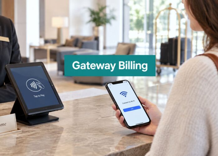
A hotel guest joins the lobby Wi-Fi, opens the captive portal, and starts the sign-in process. At that exact moment, an uplink fails. The wireless signal still appears available, but the page stalls, authentication times out, and the guest tries again. In a retail store, the same interruption might affect a payment-related Wi-Fi session. In an education or corporate BYOD environment, it can interrupt onboarding just as a user is receiving credentials.
The underlying issue may be a normal redundancy mechanism doing its job. Spanning Tree Protocol prevents switching loops, but the original version can take long enough to recover that users notice every failure. Rapid Spanning Tree Protocol keeps the same basic protection while negotiating a new forwarding path much faster.
That makes the stp vs rstp decision more than a switch setting. It affects captive portals, social WiFi onboarding, authentication workflows such as IPSK and EasyPSK, and the experience people have when they depend on your network.
What Happens When Your Network Drops a Port
Friday evening is a demanding time for a hotel network. Guests are checking in, staff are using connected systems, and visitors are opening the guest Wi-Fi page from phones and laptops. A switch port flaps somewhere in the access layer, and traffic briefly stops while the network decides which redundant path should forward frames.
With classic STP, the interruption can feel surprisingly long. Network downtime during peak hours in hospitality venues can reduce guest satisfaction scores by up to 35 percent, according to a 2024 industry survey of over 600 properties. That figure makes the technical problem easier to understand: a short wiring or switch event can become a visible service failure when it happens during a busy guest interaction.

Why guest authentication feels the outage
A captive portal usually requires several steps to complete successfully. The client associates with an access point, receives network access appropriate for onboarding, reaches the splash page, submits details or credentials, and then receives authorization. A disruption during any of those steps can look like a bad password, a broken portal, or an unreliable Wi-Fi service.
That matters for social login, social WiFi, voucher access, and authentication methods such as IPSK and EasyPSK. Users don't see spanning-tree states. They see a page that doesn't load or a login that sends them back to the beginning.
A useful troubleshooting companion is this guide to MAC address flapping and network connectivity issues. MAC movement and spanning-tree events can have different causes, but both deserve attention when wireless clients report intermittent access.
Practical rule: Treat convergence as part of the user experience. If a redundant-link failure interrupts authentication, the network has failed from the user's perspective even if recovery eventually completes.
The choice between STP and RSTP determines how long that recovery takes and how predictable it is. The protocols don't replace good cabling, stable switching, or careful portal design, but they decide how the Layer 2 network responds when a path changes.
Spanning Tree Protocols Explained Simply
Ethernet networks often contain redundant links because a single cable or switch failure shouldn't isolate an entire area. The problem is that redundant Layer 2 paths can create a loop. Broadcast and unknown-unicast frames may circulate repeatedly, consuming bandwidth and switch resources until the LAN becomes unusable.
STP solves that problem by building a logical tree. Switches exchange Bridge Protocol Data Units, or BPDUs, elect a root bridge, and select the preferred forwarding paths. Redundant links remain available as backups, but STP blocks the paths that would create a loop.
Think of a road network with several routes between the same towns. STP closes selected roads so vehicles don't drive around an endless circuit. If the main route fails, the protocol eventually opens a backup route after confirming that doing so won't create a loop.
The original standard has an important place in networking history. The IEEE standardized STP as 802.1D in 1990, based on Radia Perlman's spanning-tree algorithm. It remained the original Ethernet loop-prevention standard for more than a decade, until RSTP arrived as IEEE 802.1w in 2001 and was folded into IEEE 802.1D-2004.
How classic STP changes state
Classic STP uses port roles and states to control forwarding. A port may be selected as a root port, designated port, or blocked port. When the topology changes, the replacement path moves through listening and learning before it forwards traffic.
That caution protects the network, but the process depends heavily on timers. The switch waits to learn whether the old path has really disappeared and whether the new path is safe. In a stable, small LAN, that may be acceptable. In a busy hotel, school, store, or office, users experience the waiting directly.
For readers who want a broader explanation of how devices exchange information, Reworx Recycling's communication protocols guide provides useful context on protocol-based communication. The same general principle applies here: devices follow shared rules so independent systems can coordinate without creating ambiguity.
What RSTP changes
RSTP preserves the loop-prevention goal but improves the decision process. Instead of relying only on the full legacy timer sequence, it uses a proposal and agreement handshake between neighboring switches. The switches can confirm a safe alternate path and move it toward forwarding without waiting through every traditional transition.
RSTP also gives the protocol clearer ways to describe backup paths, including alternate and backup roles, along with edge ports for appropriate endpoint connections. The terminology and behavior are more precise, which helps the network react quickly while retaining protection against loops.
For a focused introduction, this spanning tree protocol guide explains the role of STP and its rapid evolution in practical terms. The central idea is simple: STP prevents loops, while RSTP performs the same safety task with a faster response to change.
STP vs RSTP Side by Side
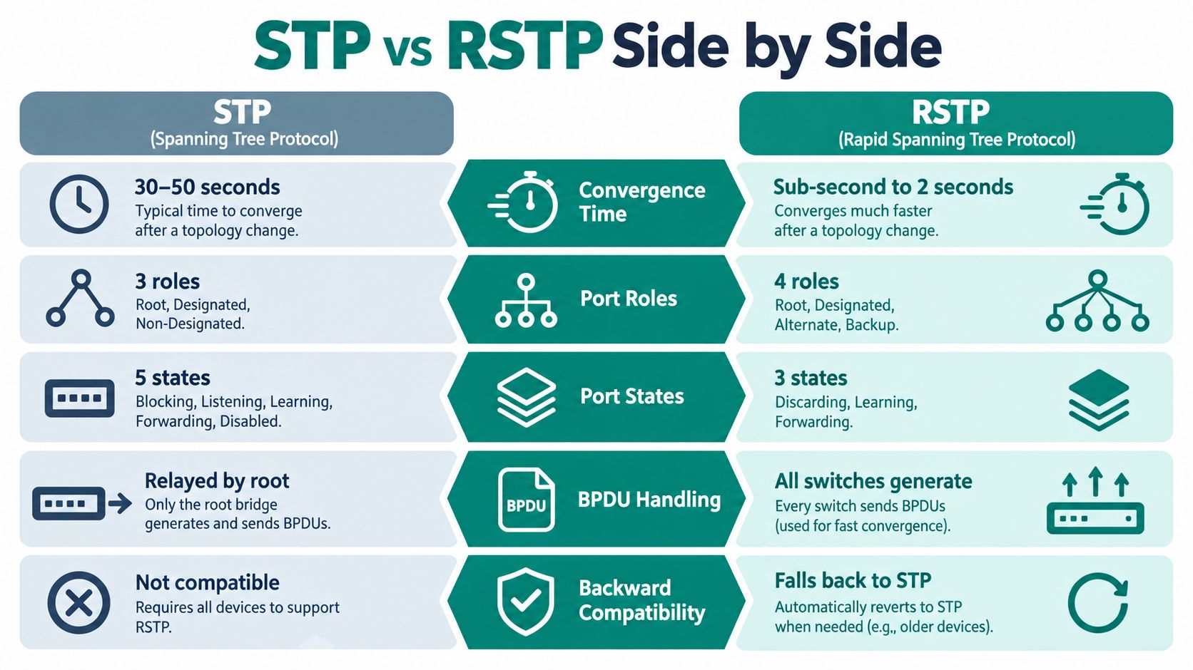
The most useful stp vs rstp comparison starts with the operational details, not just the names. Both protocols build a loop-free forwarding topology, but they differ in how they represent ports, handle state changes, and recover from failure.
| Criterion | STP (802.1D) | RSTP (802.1w) |
|---|---|---|
| Convergence time | Commonly about 30 to 50 seconds after a topology change | Sub-second to about 1 to 2 seconds on suitable point-to-point links |
| Port roles | Root, designated, and blocked | Root, designated, alternate, backup, and edge roles |
| Port states | Blocking, listening, learning, forwarding, and disabled | Discarding, learning, and forwarding |
| BPDU handling | Traditional behavior relies on the root's information being relayed through the tree | Switches generate and process BPDUs more actively |
| Backward compatibility | Operates as the classic protocol | Can interoperate with STP, but may fall back to slower behavior |
Roles give RSTP more information
Classic STP describes a redundant port broadly as blocked. RSTP can distinguish an alternate port, which provides another path toward the root, from a backup port, which backs up a designated path on the same shared segment. That distinction helps the switch identify which interface can take over when the active path fails.
RSTP also uses the edge concept for ports connected to endpoints rather than other switches. An edge port can move toward forwarding quickly when it connects to a known endpoint, provided the design protects the network from accidental loops.
States remove unnecessary waiting
STP's listening and learning phases form part of the traditional transition sequence. RSTP simplifies the active state model to discarding, learning, and forwarding, while its handshake process coordinates the change with neighboring switches.
That doesn't mean every RSTP event always finishes instantly. Link type, topology, device behavior, and the kind of failure all matter. The advantage is that RSTP has a mechanism designed to confirm the new path quickly instead of treating every repair as a timer-only exercise.
The important qualification is compatibility. RSTP can communicate with classic STP equipment, but a link involving legacy behavior may lose much of the speed that motivated the upgrade. A network can therefore be configured for rapid spanning tree while still producing slow recovery at a particular boundary.
Why Convergence Speed Changes Everything
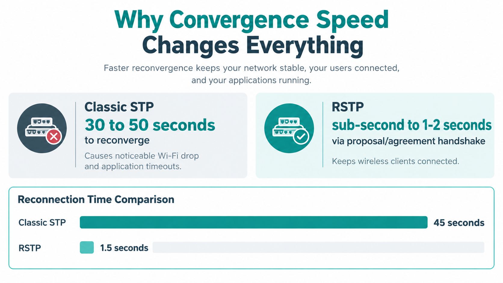
Classic STP commonly needs 30 to 50 seconds to reconverge after a topology change, while RSTP can converge from sub-second to about 1 to 2 seconds on point-to-point links, depending on the design and network conditions. The figures are documented in this technical comparison of STP and RSTP convergence, which also describes the proposal and agreement mechanism behind RSTP's faster behavior.
Another failure type needs separate attention. If a switch loses BPDUs from a neighbor, RSTP commonly detects the loss after roughly three missed hello intervals, or about 6 seconds with the default 2-second hello time. That remains materially faster than the classic STP sequence, where Max Age and Forward Delay can extend recovery toward 50 seconds, as described in this STP and RSTP timing reference.
The user doesn't experience seconds as abstract units
A guest trying to open a captive portal isn't waiting for a diagram to settle. They're deciding whether to retry, switch to cellular data, ask staff for help, or leave the page. During a hotel check-in, repeated failures can make the Wi-Fi service appear broken even when the access points and portal are operating correctly.
The same pattern appears in other sectors:
- Hospitality: A guest may lose the page used for social login, voucher acceptance, or consent before authorization completes.
- Retail: A customer or employee device may lose a Wi-Fi session near a service desk or checkout area.
- Education: Students using campus guest access or social WiFi onboarding may need to restart the connection process.
- Corporate BYOD: A personal device may fail while receiving access through a guest portal, identity provider, IPSK, or EasyPSK workflow.
RSTP doesn't guarantee that an application will preserve every session. It reduces the Layer 2 interruption, which gives higher-level services a better chance of continuing without a visible failure.
Faster recovery also helps diagnosis
A slow event can produce a confusing chain of symptoms. The portal may be blamed because the splash page timed out. The authentication service may be blamed because the user sees an error. The access point may be blamed because the client disconnects. Faster convergence narrows the disruption window, making it easier to distinguish a switching event from a portal, RADIUS, directory, or client problem.
Teams that track availability, client experience, and authentication behavior can use network performance metrics for Wi-Fi environments to correlate user reports with infrastructure events. That correlation matters more than declaring that a network is rapid.
Where Each Protocol Fits Best
A small, mostly static LAN with little redundancy may continue to function acceptably with classic STP. If the network has few users and topology changes are rare, the longer recovery period may not justify an immediate redesign.
The decision changes when the access layer supports mobile clients, several VLANs, redundant uplinks, guest Wi-Fi, or business-critical wireless workflows. Hospitality, retail, education, and corporate BYOD environments all create more opportunities for users to notice an interruption because people connect and authenticate throughout the day.
Match the protocol to the service
A hotel using Cisco Meraki access points may present an open SSID and send guests to a splash page for sign-on. A RADIUS-backed design can authenticate users through the guest workflow, while a custom captive portal can support branding, consent, social login, or marketing collection. Cisco Meraki documentation and deployment guidance describe this general pattern, including an open security setting, splash-page authentication, and RADIUS using UDP port 1812, as outlined in this Cisco Meraki captive portal guide.
The switching layer doesn't perform every authentication task, but it carries the traffic that lets those tasks complete. If a redundant path fails during onboarding, RSTP can reduce the chance that a client sees a broken redirect or abandoned login.
IPSK and EasyPSK serve a different access model. Instead of relying only on a shared guest password, an organization can assign more controlled credentials or keys to people, devices, rooms, groups, or services. Those workflows still depend on stable transport between access points, switches, authentication systems, and management platforms.
Don't confuse rapid recovery with traffic optimization
Both STP and RSTP still use a single spanning tree for all VLANs in the basic model. That means RSTP improves recovery speed, but it doesn't by itself provide VLAN-level path optimization or per-service redundancy design. Huawei's STP reference highlights this limitation for environments where multiple VLANs share an access layer.
A campus might therefore choose RSTP as an immediate reliability improvement and later evaluate MSTP when segmentation and scale require a more deliberate relationship between VLAN groups and spanning-tree instances. The protocol choice should follow the traffic design, not just the advertised convergence number.
For teams assessing the switching layer, this guide to managed switches explains why centralized configuration, monitoring, and control matter for networks carrying guest and corporate services. RSTP works best when administrators can see the topology and verify which devices participate in it.
Configuration and Migration Considerations
Upgrading from STP to RSTP is often technically simple, but the surrounding topology deserves more attention than the command itself. RSTP is backward compatible with classic STP, which makes staged upgrades possible. It also creates a trap: when an RSTP switch connects to a classic STP device, the link can operate with slower behavior.
This RSTP compatibility discussion describes the practical concern. Legacy switches, outsourced facility equipment, and partially refreshed networks can dilute the improvement, leaving administrators wondering why a rapid design still behaves like classic STP.
Audit the path before changing modes
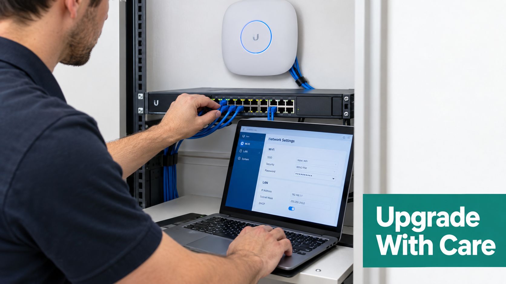
Start with an inventory of every switch and inter-switch link in the Layer 2 domain. Don't check only the core and distribution devices. A single older switch in a remote room, leased facility, or service area can affect the behavior of the path that carries guest or corporate VLANs.
Use a deliberate migration sequence:
- Map the topology. Identify redundant links, trunks, access-layer switches, and any equipment managed by another team.
- Verify protocol support. Confirm that each relevant hop supports IEEE 802.1w or an equivalent RSTP implementation.
- Choose the root intentionally. Place the preferred root where the topology and traffic design support predictable forwarding.
- Protect edge connections. Apply edge behavior only to ports that should connect to endpoints, not to links that may connect to another switch.
- Test failure paths. Validate both direct link loss and indirect neighbor failure during a maintenance window.
- Watch authentication. Check captive portal redirects, RADIUS-backed access, IPSK, EasyPSK, social login, and social WiFi flows while testing failover.
Decide whether RSTP is enough
Stay with classic STP when the network is small, stable, and tolerant of a long recovery interval. Choose RSTP when users depend on continuous access, redundant links support important services, or a topology change would visibly disrupt Wi-Fi onboarding.
Consider MSTP when the network's main problem is not only recovery speed but also how several VLANs share redundant paths. RSTP can make a single tree recover quickly, but it doesn't remove the architectural limits of a single tree.
Platform-specific implementation varies. Teams working with Cisco switching can use this Cisco switch configuration resource as a practical reference, then confirm the exact syntax and safeguards in the documentation for the installed software version.
Frequently Asked Questions
Can STP and RSTP run together safely
They can interoperate, but compatibility doesn't preserve the full rapid benefit. The RSTP side may use slower behavior on the boundary with a classic STP device, so mixed operation should be treated as a migration state to document and monitor.
Is STP still relevant in 2026
Yes. Classic STP remains relevant when you encounter older switches, inherited facilities, or equipment that hasn't been refreshed. It also matters as a compatibility reference because engineers need to understand what happens when an RSTP domain meets an 802.1D neighbor.
Will RSTP fix every captive portal problem
No. RSTP addresses Layer 2 convergence, not incorrect splash-page settings, failed RADIUS requests, directory errors, DNS problems, client browser behavior, or an authentication policy that rejects a user. It can shorten the network interruption, but you still need to test the complete path from Cisco Meraki access point association through portal onboarding and authorization.
Splash Access provides captive portals for Cisco Meraki environments, with support for WPA2 and IPSK authentication, customizable splash pages, Azure AD and SAML integrations, social WiFi workflows, and API-driven onboarding. Review how those capabilities can complement a properly designed RSTP network by visiting Splash Access.