Ask three people where routing happens on a shared building network and you'll get three answers. One points at the core router, one at the firewall, one at the access switch in the comms cupboard. All three can be right, and that's exactly the problem. The difference between Layer 2 and Layer 3 switching isn't really a spec-sheet argument about which box is faster. It's a decision about where the boundary between broadcast domains and trust zones sits, and that decision follows you around for years.
Take a café with guest Wi-Fi, a card payment terminal and two staff laptops. Put all of it in one broadcast domain and a single misbehaving device can stall the payment terminal. Split it into three VLANs and now nothing talks to anything else until you deliberately route it. Same switches, same cabling, completely different network.
The people who ask this question most are network administrators in hospitality, retail, education and corporate offices, plus the teams halfway through a BYOD rollout on Cisco and Meraki hardware. They usually arrive after something broke, or just before a refresh, and they want to know whether the access layer should route.
Before you read any further, do two things. Count your VLANs, and check whether routing happens on the access switch or on a separate router. That answer shapes every design decision below.
Layer 2 and Layer 3 Switching at a Glance
The fastest way to see the split is side by side, so here's the table readers are looking for.
| Criterion | Layer 2 switching | Layer 3 switching |
|---|---|---|
| Forwards based on | MAC addresses in Ethernet frames | IP addresses in packets |
| Traffic scope | Stays inside one VLAN and broadcast domain | Moves between IP subnets and VLANs |
| Default gateway | External router or router subinterface | Switched virtual interface on the switch |
| Loop handling | Relies on Spanning Tree Protocol, which can block redundant links | Routed point-to-point links with no STP across the routed portion |
| Recovery time (Cisco design guidance) | Around 800-900 ms in an optimized access design | Under 200 ms in a routed access design |
| Typical placement | Access switches with VLANs extended toward the distribution layer | Routing at the access or distribution layer with the subnet boundary near the edge |
| Best fit | Single-subnet access and legacy apps that need VLAN extension | Multi-VLAN campus, hospitality and retail networks with segmentation |
Read it as two different jobs rather than two quality tiers. A Layer 2 switch is a very good postman inside one street. A Layer 3 switch is the sorting office that also knows which street a parcel belongs on.
The rows that actually decide your design
Two rows carry most of the weight. The default gateway row tells you where policy lives: if the gateway is a router subinterface on a trunk, all inter-VLAN access control and DHCP relay concentrate on that device. Move the gateway to a switched virtual interface on the switch and the same policy now lives on every access switch you own.
The loop handling row decides what happens at 9am on a Monday when a cable goes bad. Spanning Tree Protocol keeps a Layer 2 topology loop-free by blocking redundant links, which means recovery depends on the shape of the tree rather than on a clean routing decision. Routed links sidestep the tree entirely between switches.
What changes for you in practice
If traffic ever crosses VLANs, routing happens somewhere. There's no design where guest Wi-Fi reaches a print server by magic. The question is whether that routing point is one device in the core or a dozen gateways spread across the building.
Practical rule: decide the routing point before you buy hardware, not after. It's cheap to design in and expensive to retrofit into live switches.
Which row matters most depends on your building. Voice, payment and captive portal logins punish slow recovery. Guest, student and BYOD networks punish weak segmentation. Most sites need both, and that usually points at a Layer 3 boundary near the access switch with a firewall behind it.
How Layer 2 Switching Forwards Frames
Layer 2 forwarding is refreshingly mechanical. Once you can picture the five steps, every odd behaviour in a flat network starts making sense.
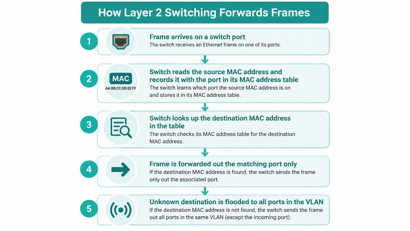
- A frame arrives on a port. The switch reads the Ethernet header and nothing else. No IP address is consulted, which is why a Layer 2 switch forwards at wire speed with almost no processing overhead.
- It records the source MAC address. The switch writes that MAC address and the port it arrived on into its MAC address table. Nobody configures this. The switch learns the layout of the network just by watching traffic arrive.
- It looks up the destination MAC address. If the table has an entry, the switch knows exactly which port to use.
- Known destination goes out one port. Unknown or broadcast gets flooded. A frame for an address the switch hasn't learned yet, or a broadcast frame, goes out every port in the same VLAN. That flooding is normal, and it's why oversized broadcast domains get noisy.
- Idle entries age out. Addresses that stop sending traffic are dropped from the table after a period of inactivity, which by default on most Cisco switches runs to about 300 seconds. That's why the first packet after silence often gets flooded.
The reason each VLAN is its own broadcast domain follows straight from step four. A guest VLAN and a staff VLAN on the same physical switch never see each other's broadcasts, because the flooding stops at the VLAN boundary. This is what VLANs are for, and it's worth reading up on how VLANs work before planning segmentation for a guest network.
Trunks and the hotel example
Take a hotel with three VLANs: guest Wi-Fi, staff devices and point-of-sale terminals. The access switch keeps them apart locally, and the uplink carries all three to the rest of the building as a trunk, tagging each frame with an 802.1Q identifier so the far end knows which VLAN it belongs to. Tagging preserves the separation across the uplink without a separate cable per VLAN.
The misunderstanding that costs people weekends
A Layer 2 switch cannot route between VLANs, no matter how many ports it has or how many VLANs you create on it. Adding a fourth VLAN to a 48-port switch doesn't create connectivity, it creates a fourth isolated network waiting for a gateway. Teams hit this after a segmentation project and conclude the VLANs are broken. They aren't. The routing was never there.
To see the forwarding decision happen, check the MAC address table for a single port on your own switch and watch entries appear and age. Two minutes of that explains more than any diagram.
How Layer 3 Switching Routes Between Subnets
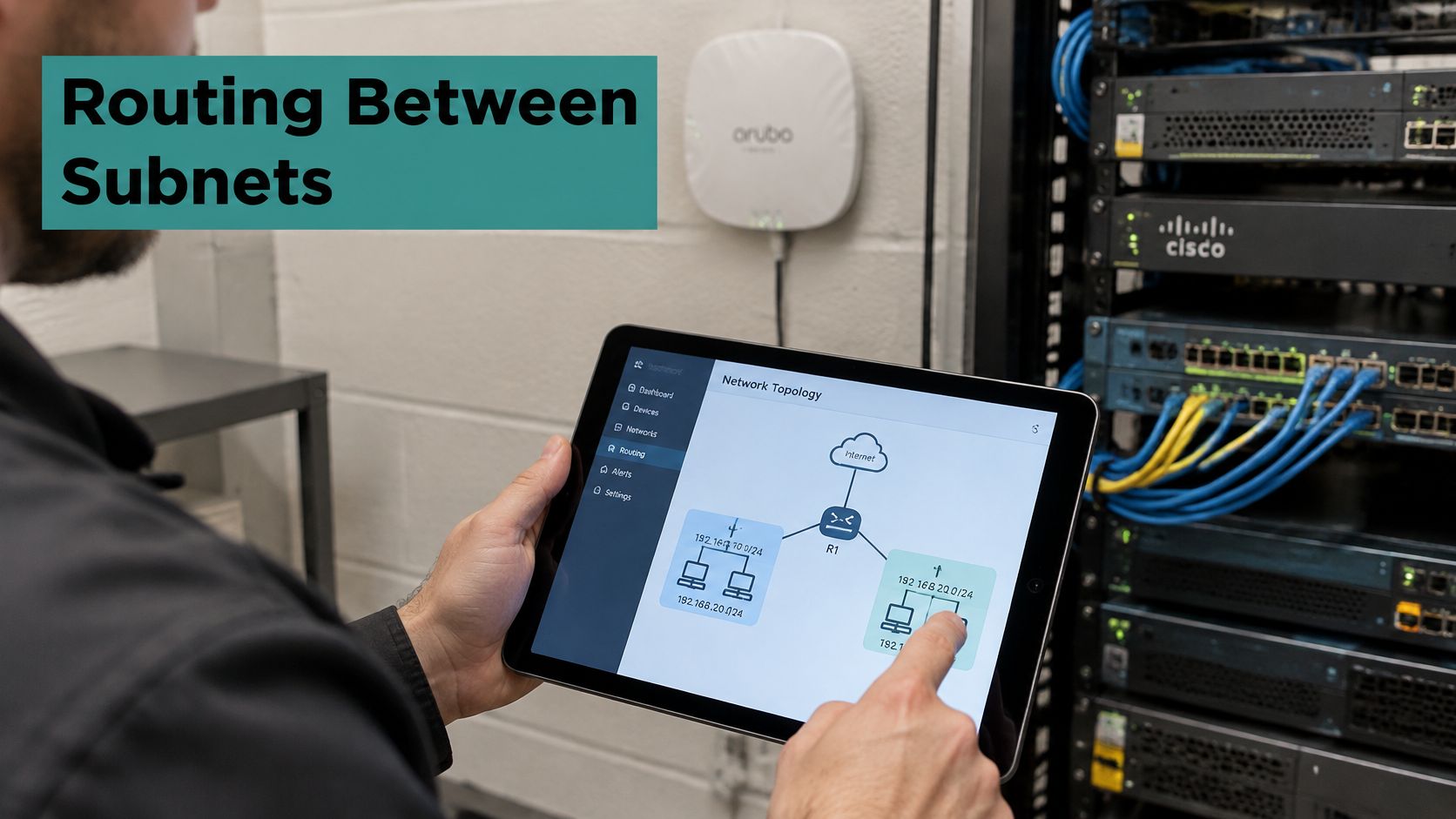
A Layer 3 switch does the same frame forwarding as any other switch for traffic inside a VLAN. The moment a packet is addressed to a different subnet, it reads the IP header, checks the routing table and forwards the packet out the right interface. Same hardware, one extra decision.
The gateway for each VLAN is a switched virtual interface, an SVI, living on the switch itself. Cisco's comparison of Layer 2 and Layer 3 switching puts it plainly: a Layer 3 switch provides one gateway per VLAN and routes between those subnets, while a Layer 2 environment relies on an external routing device for that job. The arithmetic is direct. Five active user VLANs need five corresponding Layer 3 gateway interfaces when the routing is done on the switch.
In a Layer 2 design, the same work lands on a router, usually configured as a subinterface on a trunk link. That works fine. It just concentrates everything in one place.
One gateway per VLAN, and why location matters
Where the gateway sits decides three things at once: where DHCP relay points, where routing decisions are made, and where your access-control lists are applied. That's not a detail you can leave to chance. If the gateway for guest Wi-Fi is on the switch in a back office and the gateway for staff devices is on the core router, your policy is now written in two places by two people.
Here's the retail case. A store runs five VLANs: point-of-sale terminals, security cameras, guest Wi-Fi, staff handhelds and the back-office system. With routing on the switch, each VLAN gets its own gateway, cameras stay on a quiet segment with no path to the internet, guests reach the portal and the internet and nothing else, and staff handhelds reach the inventory system but not the payment VLAN. Each gateway handles its own traffic and enforces its own rules.
Cisco Meraki MS switches can route between VLANs once Layer 3 is enabled on the network, which lets teams keep routing close to the access layer instead of hauling every subnet back to a central appliance. Devices also need correct addressing to make any of this work, so it's worth being clear on what a subnet mask actually does before you assign gateways.
The trade-off nobody mentions
Routing at the edge shortens paths and simplifies gateway placement. It also spreads configuration across every switch in the building. One inconsistent ACL on one access switch is now a security gap, and nobody notices until an audit. Consistent templates, central monitoring and a documented standard matter more in a routed-access design than in a flat one.
Management access deserves the same discipline. When you configure switches without exposing management access, put management on its own VLAN with a gateway and ACL that only your admin subnet can reach.
Verification before sign-off takes three checks. Confirm every active VLAN has a gateway interface that's up. Confirm which VLAN carries guest and staff traffic and that the access rules sit on the right gateway. Then test one device per VLAN and prove it reaches only the destinations you intended.
Failover Speed and Loop Prevention Compared
Failover speed stops being abstract the first time a card decline turns out to be a reconverging network. Voice calls drop, portal logins time out and terminals retry while the topology settles.
A Layer 2 access design depends on Spanning Tree Protocol to prevent loops, and STP does that by blocking redundant links. Failure behaviour then depends on the exact shape of the tree, which is why two buildings with apparently identical designs can behave differently. Layer 3 routed access uses point-to-point adjacencies instead, shrinking failure domains and removing STP from the routed portion altogether. Cisco campus design guidance puts an optimized Layer 2 access design at roughly 800 to 900 milliseconds to converge, against under 200 milliseconds for a Layer 3 routed-access design, roughly a fourfold improvement.
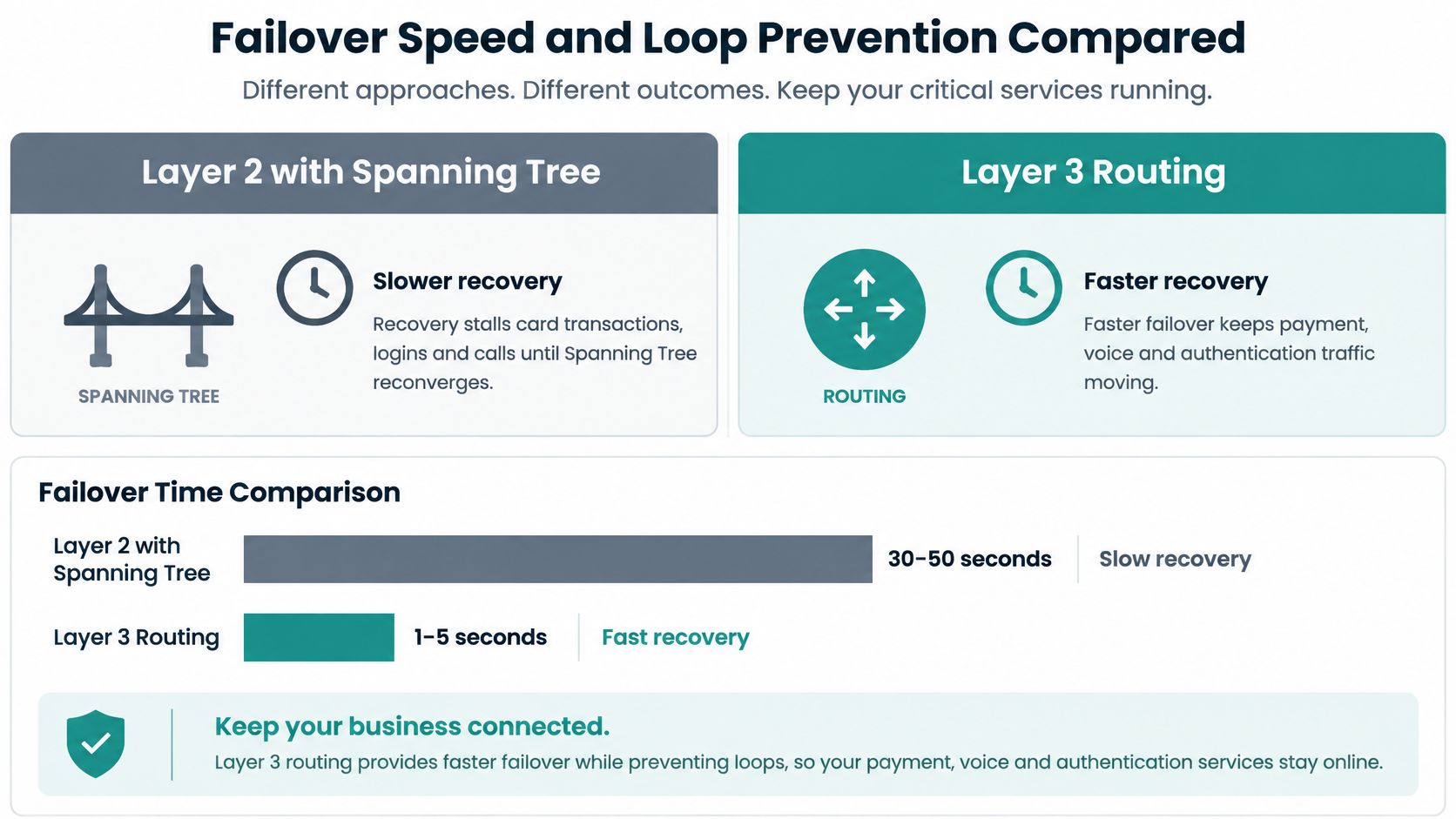
The real win: a smaller failure domain beats a smaller number. When the Layer 3 boundary sits at the access switch, a dead switch takes down its own segment and nothing else.
Picture a café whose back-room switch fails. In a wide Layer 2 VLAN, the STP recalculation can disturb the card terminal and the guest Wi-Fi elsewhere in the building. With a routed boundary at the access switch, that failure stays with the local switch.
Layer 2 still earns its place. Legacy applications, centralized services and some mobility designs need VLAN extension, so keep Layer 2 where that requirement is explicit rather than default. If you're weighing up the loop-prevention side, STP versus RSTP is the place to start tuning.
If a link or switch failure shouldn't affect other areas of the building, put the Layer 3 boundary near the access switch.
Where Routing Ends and Security Policy Begins
A Layer 3 switch is not a firewall. Say it out loud before a segmentation project, because the assumption shows up in almost every design review and it's expensive to unpick later.
A multilayer switch routes traffic efficiently between VLANs. It does not automatically apply inter-VLAN access control, internet policy, identity-based authorization or inspection. Those may still belong on a firewall or security gateway. Cisco's guidance on Layer 3 switching and VLANs frames the key question well: not "which is faster" but "where should routing happen" in a guest, staff, IoT or student network.
Consider a hotel or campus with guests, point-of-sale systems, cameras, building controls and employees all on separate VLANs. Layer 2 keeps each broadcast domain isolated, which is useful. But traffic between those VLANs needs Layer 3 routing and an explicit security policy that says who may reach what. Isolation without policy is just tidiness.
The four factors that set the boundary
The right design depends on trust boundaries, east-west traffic, multicast requirements, and whether the network needs inspection rather than routing alone. East-west traffic is the one people forget: cameras talking to a recorder, tills talking to a stock system, staff laptops talking to a file server. That traffic never leaves the building, and it's often the most sensitive.
Moving gateways into the access layer shortens paths, and it also distributes policy enforcement and troubleshooting across more devices. Decide whether your team can support that spread.
Multicast is the quiet constraint. Video distribution, paging systems and some building-control platforms behave badly across routed boundaries unless you configure it deliberately. Check before you route.
A question set for every VLAN
Work through these for each VLAN before you touch a gateway setting. Answer them in writing, because they become your firewall rules and your ACLs.
- Who should reach it? Name the groups and devices, not the building. "Guests on the portal" is a group. "Everyone on the second floor" isn't.
- What must it never touch? Payment systems, HR shares, camera recorders and building controls usually top this list.
- Where is its policy enforced? Router, switch ACL or firewall, and say which one out loud so nobody assumes someone else did it.
- Does it need inspection, not just routing? Anything crossing to the internet from a guest or BYOD segment does.
- Who troubleshoots it at 2am? If the answer is unclear, the design is too distributed.
That last question tends to change people's minds about moving every gateway to the edge. For most retail, hospitality and education sites, a Layer 3 boundary near the access layer plus a firewall behind it gives the clean split between routing and enforcement. The segmentation best practices guide is a sensible next read once you've mapped your trust zones.
Guest Wi-Fi Authentication on Top of VLANs
VLAN separation is a Layer 2 mechanism, not an authentication system. Ports in different VLANs cannot exchange data without a Layer 3 routing device, and that's all a VLAN does. It says nothing about who the user is.
Authentication is what sits on top. Cisco's captive portal marketplace materials describe guest and BYOD sign-in options including employee sponsorship, SMS codes, social network login, QR codes and corporate directories such as Microsoft Azure and Google. Those are identity methods. They decide who gets on. The VLAN design decides what they can reach.
Here's the flow in the order it happens. A guest phone joins the store SSID and lands on the guest VLAN. The controller redirects it to the captive portal, and the portal identifies the user through social Wi-Fi login, an SMS code or a voucher. Once authorized, the Cisco Meraki VLAN and Layer 3 policies decide where that user's traffic can go. The portal never grants reachability by itself.
IPSK and EasyPSK, and where they fit
IPSK gives each device or group its own pre-shared key, so access becomes individual rather than shared. EasyPSK applies the same idea at scale across larger deployments without a manual key list per site. Splash Access builds captive portals and IPSK workflows that sit alongside Meraki networks, and its education and co-working modules map users to personal VLANs through directory groups.
Three patterns show why the VLAN plan has to come first.
Student housing. Each resident gets a personal key mapped to a dorm VLAN, so one student's compromised laptop doesn't expose a floor of devices.
Retail guest Wi-Fi. Social login captures marketing consent for the visitor on the guest VLAN, while point-of-sale stays on its own segment with no path to guest traffic.
Corporate BYOD. Authenticated personal devices land in their own VLAN with a timer and group level that reflects their role, not their building.
If you want the mechanics, guest Wi-Fi authentication covers the portal side. Just remember that authentication does not replace routing and firewall policy. Decide the VLAN, then choose the login.
Choose the Switching Layer Your Network Needs
The right layer comes down to three things: how many VLANs you run, how far traffic has to travel between them, and how fast failover has to be. Situations repeat across the industries this question comes from, so here's the practical version.
| Situation | Recommended layer | Why it fits |
|---|---|---|
| Single-floor cafe with guest Wi-Fi only | Layer 2 access with a router for internet access | Few VLANs and low inter-VLAN policy needs |
| Hotel with guest, staff and point-of-sale networks | Layer 3 at access or distribution with a firewall for policy | Isolated VLANs with fast recovery for payments and authentication |
| Retail chain with point-of-sale, cameras and guest Wi-Fi | Layer 3 boundary per store with central firewall policy | Keeps payment and camera traffic separate from guests |
| University with personal dorm VLANs | Layer 3 routed access with IPSK per student | Per-student isolation and group-based access policies |
| Corporate or co-working office with BYOD | Layer 3 routing with authenticated VLANs | Role-based access and personal business VLANs |
| Legacy application that requires VLAN extension | Layer 2 only for the affected VLAN | Keeps the existing design working while limiting Layer 2 scope |
Then work through five steps in order.
- List your VLANs and what each must reach. Write the destinations down. This list becomes your gateway count and your ACL plan.
- Mark which links need fast failover. Anything carrying voice, payments or captive portal logins goes on the list.
- Decide where the gateway sits. One router, or an SVI per VLAN on the access switches. Pick one pattern and standardise it.
- Place the firewall and authentication policy. Routing moves packets, security decides who may send them.
- Test failover before you go live. Pull a link during a maintenance window and time how long a terminal takes to reconnect. If it stalls, you've found the answer before your customers did.
If you're running Cisco Meraki hardware, walk the VLAN plan through with your Cisco Meraki partner or internal team before you change the access layer, and prove guest, BYOD and payment traffic behaviour at a test site first. Splash Access works closely with Cisco Meraki on exactly these rollouts.
Splash Access provides captive portals that are instantly deployable Wi-Fi login systems integrated directly into the Meraki Cloud, so guest and BYOD onboarding runs on the VLAN design you've already built. Its IPSK and EasyPSK workflows map users and device groups to the right network segment without a shared password floating around the building. If you're planning a segmentation change and want the portal and authentication layer to match it, visit Splash Access and see how the pieces fit together.